Happy New Year Everyone!
 For the last ten weeks I’ve been learning functional programming and Haskell through an edX MOOC offered through Delft University (DelftX) in the Netherlands. (TU Delft is The Netherland’s equivalent to MIT in the US) Check out the YouTube video on the course here. That’s why I haven’t been creating new posts for this blog. Now it’s time to catch up! So, I’ve created a maze game that explores the major principles in design pattern programming using a State design pattern.
Play with a Purpose
This particular maze follows a trail of OOP and Design Pattern principles to the end of the maze. As you find each principle, you will see an image and a statement of the principle. For example, the first part of the maze moves through the S.O.L.I.D. acronym to help you remember five basic OOP principles. When you find the room with the Interface Segregation principle, Figure 1 shows what you will see:
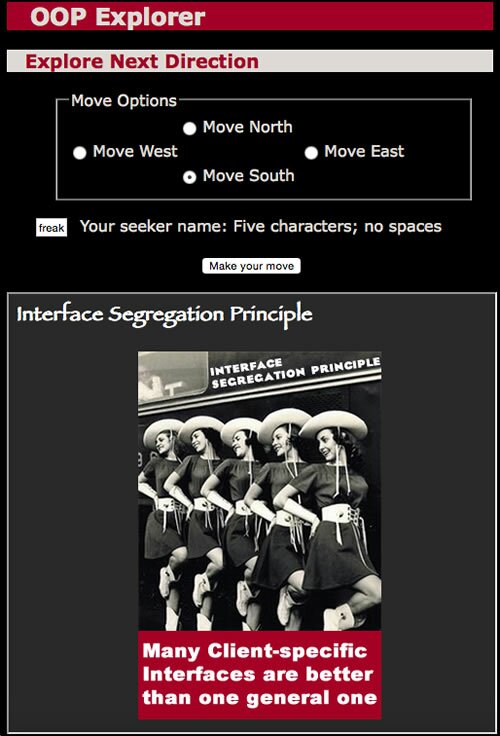
Figure 1: A room in the maze with an OOP principle.
Movement is controlled by a set of four ratio button and a “Make Move” button. Each user must include a unique user name where the moves for the user are stored in a Json file. A State Design Pattern helps not only in creating this maze, but it is a template for any 5 x 5 maze!
Why use a State Pattern on a Maze?
In building a D&D style maze, I started out with a blank sheet of paper and sketched out a 5 x 5 maze shown in Figure 2 (with labels).
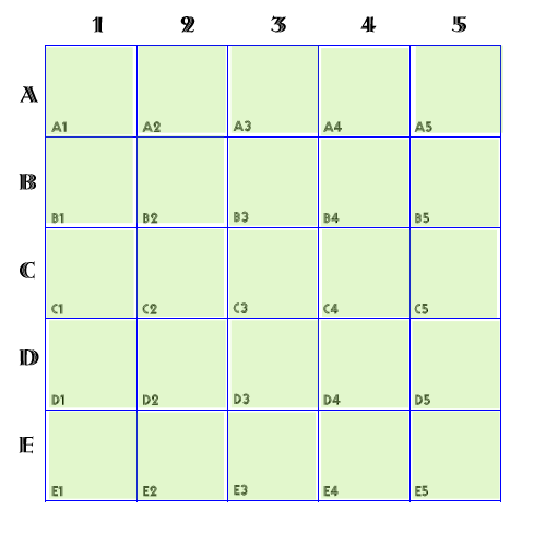
Figure 2: The 5 by 5 Matrix — coordinate values will become class names.
By picturing the matrix as being made up of 25 different states, the reason for using a State design pattern starts to take shape. If each grid square is a state, we can create code that determines what happens to the player who moves into a given state (square).
Adding Start/Finish Points and Trouble
You can decide which states will be the starting and ending states simply by designating them as such. As you can see in Figure 3, the game starts in B1 and ends in D5. The next step is to add back-to-the-start traps. These represent any kind of booby-trap you care to add to make the game interesting. You want to add enough to make the player pay attention but not so many as to make it impossible. Figure 3 shows six sequential traps–game re-start conditions that must be avoided.
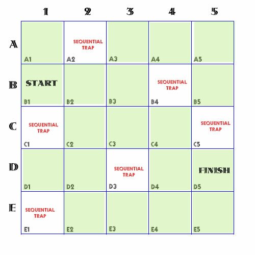
Figure 3: Add start and end states and booby-traps.
In building your maze, keep in mind that for the player, it will seem like a cavern; not the chessboard that you can see.
Movement Options: Castle, Bishop or King?
The basic movement options are pretty much like a castle, bishop or king in chess. The rules are up to you. I chose what might be called a castle 1-step. Each move, the player moves into a different room in a cavern, moving North, East, West or South. No diagonal (bishop-type) moves are allowed.
Knowing your movement option, you can then set up blocks. These are barriers between two rooms in a cavern and can be anything you want. They differ from traps in that no penalty is applied. All of the exterior sides of the matrix are blocks. For example, a player in D1 cannot go west (to the left) because it is out of the matrix boundaries. However, you can add more barriers as shown by the red bars in Figure 4:
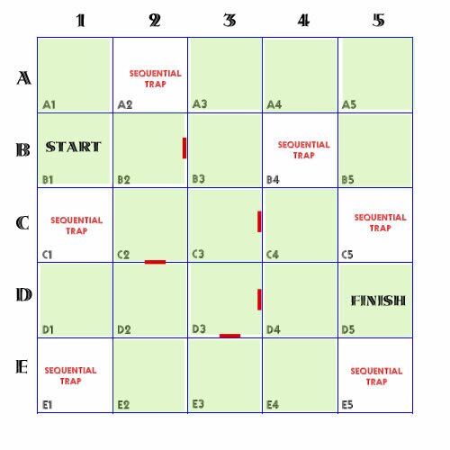
Figure 4: Added barriers indicate which cells cannot be traversed directly.
Tracing a Path
Once the maze is completed, I used direction arrows to show each step from the beginning to end. This helped in writing the code as each state to be entered called the appropriate feedback. The feedback was either text and graphic as shown in Figure 1 or just text feedback. Figure 5 shows the maze with the intended path. As the player moved along the path a different principle would appear.
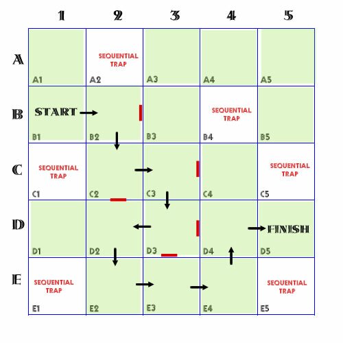
Figure 5: Arrows showing the path helped in writing the code.
All of this was preliminary to creating the maze with the State pattern and the code to run it.
From Conception to Code
The next step was to create a set of files (that would become the state classes) for each cell in the matrix. Rather than laying out the State pattern diagram, I created files for the 25 states I wished to use and arranged them as a maze. Figure 6 shows the state files, named A1State…E5State. Figure 6 shows their layout on the desktop:
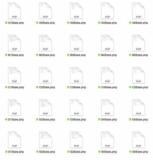
Figure 6: Starting with the state files arranged as a matrix.
Take a look at the images and try to get a picture of what the completed program will look like. In the next installment, you’ll be shown how the code for the game is worked in, and of course there will be one to play online!
Copyright © 2015 William Sanders. All Rights Reserved.
0 Responses to “The Design Pattern Principle Maze Part 1: A Story in a State Pattern”